This post will be kind of short, but I wanted to share my excitement for a recent video I saw on the Maple from Leaflabs, although it is particularly the Itead version of the opensource board, called Iteadmaple.
TKJ Electronics got one of the Iteadleaf boards and ported libraries to control a simple LCD display (2.4" SPI display for $25 is a pretty good deal) with the Iteadmaple.
The video below is the result, scroll to 8:00 minute to see the demo on the Maple.
As you can see it is pretty impressive. The sine wave generation is pretty cool and super fast to update.
Given that the cost of the two components does not exceed $60 it is a pretty good deal to do easy user interfaces for embedded systems.
I am looking forward to getting a hand on the ported libraries (TKJ mentions he is going to release them soon after a few rounds of reviews) to start working on my next little project!!!
I am also interested in getting imaging working on that maple board because it looks like it is much more powerful and as easy to code as the Arduino.
Some notes and after thoughts
a) The only drawback of the maple board is that it outputs 3.3V (good for the screen as it takes that voltage).
b) I know it is kind of ugly that china and Itead are selling LeafLab's boards for cheaper than themselves, but I guess that is something inherent from the OpenSource industry. Kudos for LeafLabs, but unfortunately most of the people will rather pay $15 less and get a clone. Less than $35 for an ARM board is a pretty good deal.
c) Arduino DUE should better hurry. Timing is key (they should know better than anybody else) and maybe by the time Arduino DUE is released and it is stable, most of us are already on board the Maple ship!!
I thought that was worth sharing for all the electronics hobbyists!!!
Let me know your thoughts.
Thursday, December 8, 2011
Wednesday, November 2, 2011
The Human side of Arduino
As I mentioned in previous postings I have been pretty busy keeping up with my life. Why? Usual suspects: work, family and hobbies. I am proud to announce though that I somehow (together with my wife) managed to gave it a shot to the making a business out of one of my hobbies.
Unfortunately the hobby I am talking about is not the one all the readers of this blog are aware of (Electronics) but building face photomosaics. What? yes Face photomosaics. And what are those, well keep reading to find out.
We recently started MosaicYourself an online based service that makes mosaics. You will say, but there are already services out there making mosaics. Yes but at MosaicYourself we make Face Photomosaics. That is mosaics where the tiles are faces.
Why faces? Well pretty easy, because faces are recognizable even if they are small, and based on our experience faces are small enough to be tiles of a mosaic but big enough to be something recognizable that gives it a personalized appearance.
Well cut the talk and let's get to the point. I thought that in order to somehow make a tribute to the Arduino and takin advantage of the LinkedIn option of MosaicYourself, we generated the mosaic we call THE FACES OF ARDUINO.
This mosaic (see below) depicts the popular microcontroller as a base images and it features the faces from the people at the Arduino Playground group on LinkedIn as tiles.
The picture below does not show enough detail to appreciate the details of the tiles, follow this link to see the picture in the website with a mouse drag enabled zoom to see the details.

There are exactly 171 different faces and chances are that if you are a member of this group, you have a profile picture and our face detector likes it, you might be part of the picture!!
But that is not all, because in order to use the double effect of the mosaic (detail vs overall picture), at MosaicYourself we also offer zoomout videos like the one below, where we go from detail to full picture to have a better effect.
The zoom-out video example below is also a picture of the Arduino we used from Daniel Andrade's HD pictures from the Arduino. This particular mosaic contains 190 faces from the same group on LinkedIn, so if you did not find yourself in the last mosaic, you might in this one!! (See links below). See the mosaic with zoom tool here
So hopefully you like the concept and want MosaicYourself to use your picture library to extract faces and build a nice mosaic for you. Or maybe use the faces of your LinkedIn contacts to make the logo of your company.
If you are interested we make the business by selling the printouts (or file versions) of the mosaics, so you can purchase any of those two Arduino mosaics at our store, or directly from the links below
- Purchase the Faces of Arduino mosaic in a poster
- Purchase the Arduino Macro mosaic in a poster
If you are interested in the details of the Arduino mosaics follow these links
www.mosaicyourself.com/ArduinoFaces
www.mosaicyourself.com/ArduinoMacro
If you liked it (purchase from us) Like us on Facebook!!
Unfortunately the hobby I am talking about is not the one all the readers of this blog are aware of (Electronics) but building face photomosaics. What? yes Face photomosaics. And what are those, well keep reading to find out.
We recently started MosaicYourself an online based service that makes mosaics. You will say, but there are already services out there making mosaics. Yes but at MosaicYourself we make Face Photomosaics. That is mosaics where the tiles are faces.
Why faces? Well pretty easy, because faces are recognizable even if they are small, and based on our experience faces are small enough to be tiles of a mosaic but big enough to be something recognizable that gives it a personalized appearance.
Well cut the talk and let's get to the point. I thought that in order to somehow make a tribute to the Arduino and takin advantage of the LinkedIn option of MosaicYourself, we generated the mosaic we call THE FACES OF ARDUINO.
This mosaic (see below) depicts the popular microcontroller as a base images and it features the faces from the people at the Arduino Playground group on LinkedIn as tiles.
The picture below does not show enough detail to appreciate the details of the tiles, follow this link to see the picture in the website with a mouse drag enabled zoom to see the details.
There are exactly 171 different faces and chances are that if you are a member of this group, you have a profile picture and our face detector likes it, you might be part of the picture!!
But that is not all, because in order to use the double effect of the mosaic (detail vs overall picture), at MosaicYourself we also offer zoomout videos like the one below, where we go from detail to full picture to have a better effect.
The zoom-out video example below is also a picture of the Arduino we used from Daniel Andrade's HD pictures from the Arduino. This particular mosaic contains 190 faces from the same group on LinkedIn, so if you did not find yourself in the last mosaic, you might in this one!! (See links below). See the mosaic with zoom tool here
So hopefully you like the concept and want MosaicYourself to use your picture library to extract faces and build a nice mosaic for you. Or maybe use the faces of your LinkedIn contacts to make the logo of your company.
If you are interested we make the business by selling the printouts (or file versions) of the mosaics, so you can purchase any of those two Arduino mosaics at our store, or directly from the links below
- Purchase the Faces of Arduino mosaic in a poster
- Purchase the Arduino Macro mosaic in a poster
If you are interested in the details of the Arduino mosaics follow these links
www.mosaicyourself.com/ArduinoFaces
www.mosaicyourself.com/ArduinoMacro
If you liked it (purchase from us) Like us on Facebook!!
Monday, September 19, 2011
Memory, Imaging and Arduino
Hi All,
I am not sure at this point if anybody will be looking at the blog now that I am not showing anything interesting or documenting any project. Unluckily I did not have time to hack around with my electronics for several reasons.
My main reasons are work (as everybody's), family (I just have a kid that is going to turn 9 months in a couple weeks) and the start of my new little business of making mosaics out of people's pictures, using faces as tiles. Check it out under www.mosaicyourself.com , still working on the website but I do not seem to have time to keep up with Drupal, php and being webmaster.
Anyway, other than apologizing for not posting for the last couple of months, I wanted to highlight some of the events that have huge impact in the Electronics Hardware Hacking world (if you read this blog you are probably already aware of those anyway). Specially to what I am interested
a) Arduino goes ARM - ARDUINO DUE
That is great! I am really excited about this. I have been looking for a more powerful Arduino for a while, specially for imaging purposes in a small and affordable platform. Having Arduino in a faster form factor will allow us to do image acquisition. The chip powering the Arduino Due (SAM3U from Atmel) counts with 96MHz with 256Kb of Flash, 50Kb of Sram, 5 SPI buses, 2 I2C interfaces, 5 UARTS, 16 Analog Inputs at 12Bit.
As you all know Imaging on the Arduino requires a lot of memory (128*96/8 bytes). Now with 50KB we can even hold a color image!!
A couple of comments on this
- That might screw the plans from LeafLabs which I closely followed. I consider using them for my image procesing platform. Now (sorry guys) I will provably wait for the efford by Arduino.
- I am not sure how the programming interface will be on the Due but it potentially means that some of the shields will not be (fully or at all) compatibles. Also forget about assembly coding and restart with a new device, so the shields relying on that, such as the Video Experimenter Shield will not be compatible.
b) Memory expansion for the Arduino
Two different approaches recently came up at hackaday to extend the memory on the Arduino. I wanted to give my particular point of view on those and how do they relate to the little imaging project I did on the Arduino.
- Expanding the RAM on Arduino Mega - Unluckily this approach is not going to help much in our case as the Video Experimenter Shield, as mentioned in my blog post, is not compatible with Mega. Hackaday suggested using that expansion for image acquisition (thanks for the quote), but unfortunately that is not possible.
- Using a CPLD to get more memory - I am sorry to say but it looks like an overkill to use programmable logic to expand the memory of Arduino. I personally think I could code the CPLD with no Arduino anyway to get my image processing platform. It is versatile but I do not believe is a good solution (anybody could say that Arduino is simply not meant for image processing, I sort of agree but, still want to pull it!!). This leads to my next point:
c) Getting an Arduino-like platform on FPGA
That is definitely something I have been looking for for a while. LeafLabs are sort of pursuing that goal with the Oak, I do not want to jinx it but maybe somebody comes first or a bigger platform oversteps it (like the Due). But as always it is good to push the industry, specially the open source, although sometimes the outcome is not the best.
A kind of neat player in this platform is the Xula Board by Xess. I am kind of afine to Xess as I had them as a reference in my VHDL coding for firmware on FPGAs before, so I think they are great. The Xula Board is an Open Source effort lead by Xess to solve problems microcontrollers cannot reach (wow it looks like imaging falls in that framework).
Other than the technical I like this Xula board because
- It is cheap
- It does not need programmer
- You can use free software (the Xilinx Webpack)
- It uses FPGAs I am already familiar with
I also want to mention that Dave, at Xess is a great guy. I particularly like his blog and the way he mixes documentation and blogging. He was supper cool to send me a Xula board for my evaluation (sorry Dave for the reasons mentioned above no time yet, but I will soon get to that, I hope!).
This is it for my roundup. I have a couple of short term projects in mind I will try and pull out soon. I will keep you (reader) posted!!
Friday, June 10, 2011
Update on Arduino imaging - Processing Sketch + Video!!!
Hi all,
As promised in this post, I am posting an update on the video acquisition for Arduino. Well so based on the constructive comments on the different spots this blog was highlighted, I coded a simple Processing Sketch.
Here you can see a couple of images taken from the Processing Sketch
HERE YOU CAN DOWNLOAD A COMPRESSED VERSION OF THE PACKAGE
Including Arduino, Processing and LabVIEW drivers, images and the hardware schematics
WARNING: It is the first code I write in Processing. So it is super inefficient.
Keep in mind the following limitations
a) It takes about 8 seconds to acquire a single image.
b) The target of the image needs to be still, othewise each little level change will come from a different image and the result will be messed up.
This code needs optimization in the following items
a) Make the arduino pack the data in bytes (it currently wastes room by sending a bit per byte, but there is a story about why I do that, I'll post the solution when I get to it in the future).
b) Modify the processing sketch to read that format.
c) Currently the code acquires an image, idles for 1 second and loops. It might be wise to have some trigger event, but that is up to your application.
Video (shot with my Ipod Touch so hence the funny aspect ratio).
Down the road, my plans are
- Making the optimizations mentioned above
- Trying the flash/SD temporary storage approach
- Others
Leave comments if you guys do something related to this!!
As promised in this post, I am posting an update on the video acquisition for Arduino. Well so based on the constructive comments on the different spots this blog was highlighted, I coded a simple Processing Sketch.
Here you can see a couple of images taken from the Processing Sketch
 |
| Me in Processing (3 bits, 128x96 SCALE 5) |
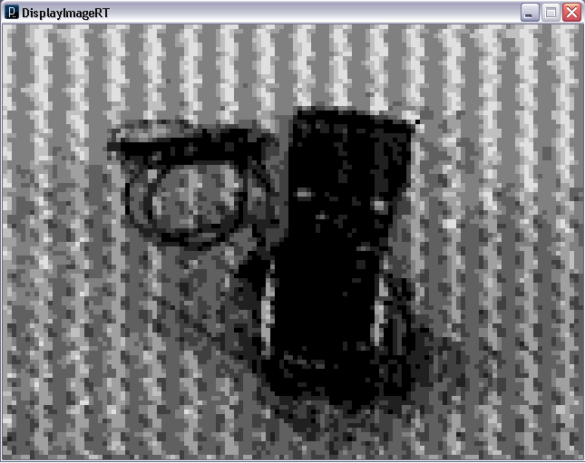 |
| My Fluke MultiMeter in the same format |
HERE YOU CAN DOWNLOAD A COMPRESSED VERSION OF THE PACKAGE
Including Arduino, Processing and LabVIEW drivers, images and the hardware schematics
WARNING: It is the first code I write in Processing. So it is super inefficient.
Keep in mind the following limitations
a) It takes about 8 seconds to acquire a single image.
b) The target of the image needs to be still, othewise each little level change will come from a different image and the result will be messed up.
This code needs optimization in the following items
a) Make the arduino pack the data in bytes (it currently wastes room by sending a bit per byte, but there is a story about why I do that, I'll post the solution when I get to it in the future).
b) Modify the processing sketch to read that format.
c) Currently the code acquires an image, idles for 1 second and loops. It might be wise to have some trigger event, but that is up to your application.
Video (shot with my Ipod Touch so hence the funny aspect ratio).
Down the road, my plans are
- Making the optimizations mentioned above
- Trying the flash/SD temporary storage approach
- Others
Leave comments if you guys do something related to this!!
Wednesday, June 8, 2011
Successful first couple of days!!!
Hey world,
Thanks for visiting. I am personally positively surprised that my last post got so much attention. So far (less than 48 hours after) the stats are impressive:
- More than 2500 visits to the site
- More than 1800 unique visitors
- People visited from all the continents
- People visited from more than 50 countries
 Here is a map of the last 500 visits as of noon of June 8 (I cannot graph more than 500 with my service).
Anyway it is all in part because I submitted it to some of the most active websites for electronic hacking. I am proud that I made it to
- Hackaday -check it out here
- Make Magazine's blog - check it out here
- Dangerous prototypes - check it out here
If somebody actually reproduces my experiment please let me know!!!
Thank you all for reading my post!!!
Thanks for visiting. I am personally positively surprised that my last post got so much attention. So far (less than 48 hours after) the stats are impressive:
- More than 2500 visits to the site
- More than 1800 unique visitors
- People visited from all the continents
- People visited from more than 50 countries

Anyway it is all in part because I submitted it to some of the most active websites for electronic hacking. I am proud that I made it to
- Hackaday -check it out here
- Make Magazine's blog - check it out here
- Dangerous prototypes - check it out here
If somebody actually reproduces my experiment please let me know!!!
Thank you all for reading my post!!!
Monday, June 6, 2011
Acquiring images from an Analog Camera using Arduino
Incredible but true, I managed to acquire images from an analog camera using an Arduino!!!! I had the inestimable help of Mike from Nootropic Design, who helped me modifying hardware and software from the video experimenter shield.


If you are interested (I bet you are) you will get the chance of doing it yourself because I am giving all the code so that you can do that at home (at your lab or for your favorite robot!!).
Feel free to skip the sections you want to skip, but I though a little bit of background is important for the whole understanding of the project.
Introduction
This project is based on the video experimenter shield by nootropic design. The idea behind this project is to be able to capture images from an Analog Video source and send them to a computer.
Big challenges
- Memory limitation on the Arduino
- Speed (perfomance) of the 8 bit microcontroller
- Dynamically changing the threshold on the board.
Limitations
- The images acquired are low resolution (128*96)
- The bit depth is adjustable. BUT THERE IS A TRADEOFF... the higher the bit depth the longer it takes to take an image.
- MONOCHROME ONLY no color.
- The code provided acquires images of 3 bits depth (8 levels). Getting more levels is pretty straighforward.
- The code is provided as is, you can use it as long as you quote me on your sources/publications. You can also contact MoviMED to get my 'professional' services (not for free).
- For the time being the PC side is coded in LabVIEW (easiest option I had available). A Processing code is on the way.
Concept
The idea behind this project was to modify the assembly code provided by Nootropic Design to
- Send thresholded images back to a PC via serial
- Dynamically change the threshold so that different thresholds give different images that can be reassembled back in the computer. That is because the arduino does not have memory enough to store more than one thresholded image.
- Initially the idea was to software control the threshold but the wise advise from Mike led me to use an external DAC (resistor ladder) to externally force thresholds.
This means that the code does the following
- Wait for a serial character to trigger the acquisition
- Set the threshold for an image
- Acquire that image
- Re set the threshold for another level and iterate
- Once all levels have been acquired (8 in the example) idle
The counter part (PC)
- Sends a character
- Waits for the images to come
- Reconstructs the image
The images
Here are some images of the MoviMED crew (me, John, Jesi and Dave) so that you can see the kind of resolution and bit depth images you can achieve. See below


What do you need?
Here is the list
- Arduino - I used the uno, it should work on the diecimila but my diecimila does not like it. My board is old (2006) though. Might try it though. It will not work on the Mega, see why.
- Video Experimenter Shield - I do not work for Nootropic Design but I recommend you buying this because it will open up lots of possibilities for your Arduino projects!!!
- 1% Resistors - Yes 1% is important. I used 95.38K resistors but any value should do. It is relevant that they are acurate for the kind of conversion needed.
- A potentiometer - The value should be in the ballpark of the resistors mentioned above.
Hardware Rig
Here is a picture of the eagle schematic of what you need to assemble on top of the video experimenter shield

You can also download this image and the eagle schematic from this link. See comments on the file behind the link below.
Arduino Code and LabVIEW counterpart
Find all the code you need to run this in the same link as before. Some comments on that though
 |
| LabVIEW front panel of the image acquisition |
 |
| LabVIEW code |
- The code is provided as is. No guarantees and I will not support it, but I can provably give you some guidelines.
- Performance - It takes about 1 second to acquire an image, so 8 level images take about 8 seconds. I can get it better by packing more info per serial packet (I am only sending a bit per byte). I will do that when I get some extra time. So far I wanted to prove the concept.
- I am planning to code the same thing in Processing. I do not program in processing but I know several other languages so I guess it is not going to take long.
- I am planning to code the same thing in Processing. I do not program in processing but I know several other languages so I guess it is not going to take long.
- The LabVIEW code requires LabVIEW 2009 and NI Vision.
- Thanks Mike for your help!!!
- Thanks Mike for your help!!!
Where to go from here
Personally I am going to work on the processing side of things so that this code is useful for the none labview guys too.
Adding more levels should be straight forward. But keep in mind, more levels, more time to acquire an image. If you move while acquiring you might get funny pics.
Great projects from here (I am already planning to do them, I will post the results here, let me know if you get there before I do).
- Store your images in a flash chip (from microchip for instance).
- Store your images in a SD card
- Do image processing, such as filters, line profiles, edge detection, etc with multi level images
- Make your little pan and tild track an object based on vision.
- Get a Maple from LeafLabs to acquire a multilevel image (major project).
- Other
Thanks
-Thanks to Mike from Nootropic Design for the help on the technical side of things
-Thanks to MoviMED, I used the cameras from work to test this code out. Check out our website and consider our AF-150x for your next RIO project!!! Consider us for any Machine Vision project!!
Initial Post
Hello world!,
Well maybe I should say
"println("Hello world")" as this is should mainly be a blog about hacking electronics with Arduino.
I guess it is one of the thousand blogs about electronics and Arduino out there but I somehow wanted a spot to display to the world some of the interesting projects I am doing.
Mainly this blog is going to contain hardware and electronic circuits I sort of put together (hack) so that I can do interesting stuff.
A little bit more about myself can be found on my website back at Grad School at UC Irvine. It is all outdated but there are some interesting (basic and outdated) and useful tutorials on Arduino, AGVs, Matlab, Google Maps and Google Earth etc.
As far as my personal info, the description on my website is pretty accurate for my pre-industry experience, but anyhow that should give you a little bit of background on where I come from.
I am currently working for MoviMED (www.movimed.com) mainly on Image Processing and Machine Vision solutions for the industry. I am lucky enough to get to hack with electronics on my job so I can call myself fortunate.
The professional bias (as you will see in the blog) points me to develop either automation or vision projects as that is what I would say my main interest is focused on. So expect Arduino, LabVIEW, image processing, electronics hacking and cameras to be the usual vocab on this blog.
Thanks for reading, I assure there will be not many frequent updates because I do not usually get free time to do my things, but I will definitely post the projects I think they are worth pursuing.
Give some feedback (that is always positive) so that I can improve/modify my posting.
Thanks in advance for reading.
Carlos
Subscribe to:
Posts (Atom)